- 您现在的位置:买卖IC网 > Sheet目录307 > ADE7758ARWZRL (Analog Devices Inc)IC ENERGY METERING 3PHASE 24SOIC
�� �
�
�ADE7758�
�Integration� Time� Under� Steady� Load�
�The� discrete� time� sample� period� (T)� for� the� accumulation�
�register� is� 0.4� μs� (4/CLKIN).� With� full-scale� sinusoidal� signals�
�on� the� analog� inputs,� a� 90°� phase� difference� between� the� voltage�
�and� the� current� signal� (the� largest� possible� reactive� power),� and�
�the� VAR� gain� registers� set� to� 0x000,� the� average� word� value� from�
�each� LPF2� is� 0xCCCCD.�
�The� maximum� value� that� can� be� stored� in� the� reactive� energy�
�register� before� it� overflows� is� 2� 15� ?� 1� or� 0x7FFF.� Because� the�
�average� word� value� is� added� to� the� internal� register,� which� can�
�store� 2� 40� ?� 1� or� 0xFF,� FFFF,� FFFF� before� it� overflows,� the�
�integration� time� under� these� conditions� with� VARDIV� =� 0� is�
�calculated� as�
�Data� Sheet�
�reactive� power� calculation.� The� total� reactive� power� is� signed�
�addition.� However,� setting� the� SAVAR� bit� (Bit� 6)� in� the�
�COMPMODE� register� enables� absolute� value� calculation.� If� the�
�active� power� of� that� phase� is� positive,� no� change� is� made� to� the�
�sign� of� the� reactive� power.� However,� if� the� sign� of� the� active� power�
�is� negative� in� that� phase,� the� sign� of� its� reactive� power� is� inverted�
�before� summing� and� creating� VARCF� pulses.� This� mode� should�
�be� used� in� conjunction� with� the� absolute� value� mode� for� active�
�power� (Bit� 5� in� the� COMPMODE� register)� for� APCF� pulses.�
�The� effects� of� setting� the� ABS� and� SAVAR� bits� of� the� COMPMODE�
�register� are� as� follows� when� ABS� =� 1� and� SAVAR� =� 1:�
�If� watt� >� 0,� APCF� =� Watts,� VARCF� =� +VAR.�
�If� watt� <� 0,� APCF� =� |Watts|,� VARCF� =� ?VAR.�
�Time� =�
�×� 0.4� μs� =� 0.5243� sec�
�0xFF, FFFF, FFFF�
�0xCCCCD�
�When� VARDIV� is� set� to� a� value� different� from� 0,� the� time�
�(36)�
�INPUT� TO� AVARHR�
�REGISTER�
�INPUT� TO� BVARHR�
�REGISTER�
�+�
�+�
�+�
�VARCFNUM[11:0]�
�÷�
�before� overflow� are� scaled� accordingly� as� shown� in� Equation� 37.�
�Time� =� Time� (� VARDIV� =� 0)� � VARDIV� (37)�
�Energy� Accumulation� Mode�
�The� reactive� power� accumulated� in� each� VAR-hr� accumulation�
�INPUT� TO� CVARHR�
�REGISTER�
�INPUT� TO� AVAHR�
�REGISTER�
�INPUT� TO� BVAHR�
�REGISTER�
�+�
�+�
�+�
�0�
�1�
�DFC� ÷4�
�VARCFDEN[11:0]�
�VARCF�
�register� (AVARHR,� BVARHR,� or� CVARHR)� depends� on� the�
�configuration� of� the� CONSEL� bits� in� the� COMPMODE� register�
�INPUT� TO� CVAHR�
�REGISTER�
�VACF� BIT� (BIT� 7)� OF�
�WAVMODE� REGISTER�
�(Bit� 0� and� Bit� 1).� The� different� configurations� are� described� in�
�Table� 13.� Note� that� IA� ’� /IB� ’� /IC� ’� are� the� current� phase-shifted�
�current� waveform.�
�Table� 13.� Inputs� to� VAR-Hr� Accumulation� Registers�
�CONSEL[1,� 0]� AVARHR� BVARHR� CVARHR�
�00� VA� ×� IA’� VB� ×� IB� VC� ×� IC’�
�01� VA� (IA’� –� IB’)� 0� VC� (IC’� –� IB’)�
�10� VA� (IA’� –� IB’)� 0� VC� ×� IC’�
�11� Reserved� Reserved� Reserved�
�Reactive� Power� Frequency� Output�
�Pin� 17� (VARCF)� of� the� ADE7758� provides� frequency� output� for�
�the� total� reactive� power.� Similar� to� APCF,� this� pin� provides� an�
�output� frequency� that� is� directly� proportional� to� the� total�
�reactive� power.� The� pulse� width� of� VARPCF� is� 64/� CLKIN� if�
�VARCFNUM� and� VARCFDEN� are� both� equal.� If� VARCFDEN�
�is� greater� than� VARCFNUM,� the� pulse� width� depends� on�
�VARCFDEN.� The� pulse� width� in� this� case� is� T� � (� VARCFDEN� /2),�
�where� T� is� the� period� of� the� VARCF� pulse� and� VARCFDEN� /2�
�is� rounded� to� the� nearest� whole� number.� An� exception� to� this�
�is� when� the� period� is� greater� than� 180� ms.� In� this� case,� the� pulse�
�width� is� fixed� at� 90� ms.�
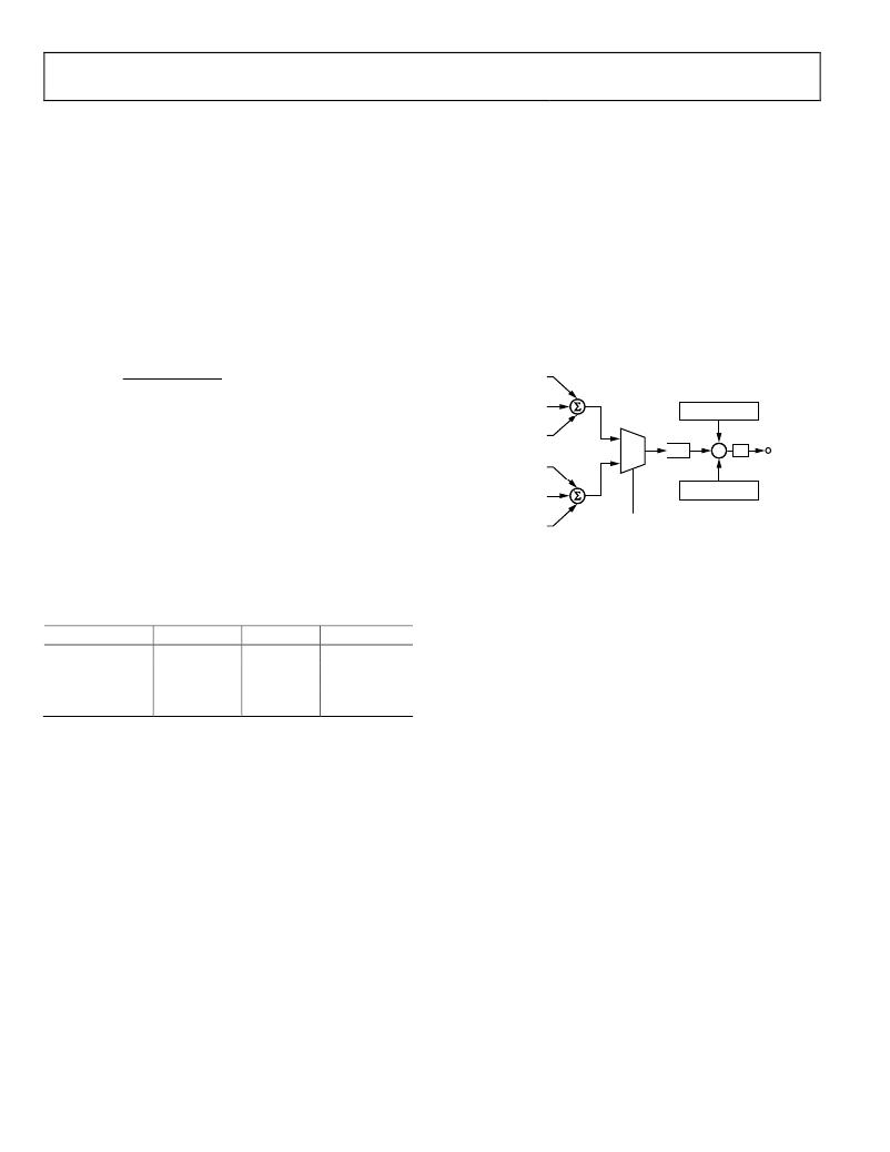
�A� digital-to-frequency� converter� (DFC)� is� used� to� generate� the�
�VARCF� pulse� output� from� the� total� reactive� power.� The� TERMSEL�
�bits� (Bit� 2� to� Bit� 4)� of� the� COMPMODE� register� can� be� used� to�
�select� which� phases� to� include� in� the� total� reactive� power� calcu-�
�lation.� Setting� Bit� 2,� Bit� 3,� and� Bit� 4� includes� the� input� to� the�
�Figure� 74.� Reactive� Power� Frequency� Output�
�The� output� from� the� DFC� is� divided� down� by� a� pair� of� frequency�
�division� registers� before� sending� to� the� VARCF� pulse� output.�
�Namely,� VARCFDEN/VARCFNUM� pulses� are� needed� at� the�
�DFC� output� before� the� VARCF� pin� outputs� a� pulse.� Under�
�steady� load� conditions,� the� output� frequency� is� directly�
�proportional� to� the� total� reactive� power.�
�Figure� 74� illustrates� the� energy-to-frequency� conversion� in� the�
�ADE7758� .� Note� that� the� input� to� the� DFC� can� be� selected� between�
�the� total� reactive� power� and� total� apparent� power.� Therefore,�
�the� VARCF� pin� can� output� frequency� that� is� proportional� to� the�
�total� reactive� power� or� total� apparent� power.� The� selection� is�
�made� by� setting� the� VACF� bit� (Bit� 7)� in� the� WAVMODE� register.�
�Setting� this� bit� switches� the� input� to� the� total� apparent� power.�
�The� default� value� of� this� bit� is� logic� low.� Therefore,� the� default�
�output� from� the� VARCF� pin� is� the� total� reactive� power.�
�All� other� operations� of� this� frequency� output� are� similar� to� that�
�of� the� active� power� frequency� output� (see� the� Active� Power�
�Frequency� Output� section).�
�Line� Cycle� Reactive� Energy� Accumulation� Mode�
�The� line� cycle� reactive� energy� accumulation� mode� is� activated�
�by� setting� the� LVAR� bit� (Bit� 1)� in� the� LCYCMODE� register.� The�
�total� reactive� energy� accumulated� over� an� integer� number� of�
�zero� crossings� is� written� to� the� VAR-hr� accumulation� registers�
�after� the� LINECYC� number� of� zero� crossings� is� detected.� The�
�operation� of� this� mode� is� similar� to� watt-hr� accumulation� (see�
�the� Line� Cycle� Active� Energy� Accumulation� Mode� section).�
�AVARHR,� BVARHR,� and� CVARHR� registers� in� the� total�
�Rev.� E� |� Page� 38� of� 72�
�发布紧急采购,3分钟左右您将得到回复。
相关PDF资料
ADE7761AARSZ-RL
IC ENERGY METERING 1PHASE 20SSOP
ADE7761BARSZ-RL
IC ENERGY METERING 1PHASE 20SSOP
ADE7768ARZ-RL
IC ENERGY METERING 1PHASE 16SOIC
ADE7769ARZ-RL
IC ENERGY METERING 1PHASE 16SOIC
ADM8843ACPZ-REEL7
IC LED DRVR WHITE BCKLGT 16LFCSP
ADP1653ACPZ-R7
IC LED DRVR PHOTO FLASH 16-LFCSP
ADP1712-EVALZ
BOARD EVALUATION ADP1712
ADP1720-EVALZ
BOARD EVAL FOR ADP1720-ADJ
相关代理商/技术参数
ADE7759
制造商:AD 制造商全称:Analog Devices 功能描述:Active Energy Metering IC with di/dt Sensor Interface
ADE7759ARS
功能描述:IC ENERGY METERING 1PHASE 20SSOP RoHS:否 类别:集成电路 (IC) >> PMIC - 能量测量 系列:- 产品培训模块:Lead (SnPb) Finish for COTS
Obsolescence Mitigation Program 标准包装:2,500 系列:*
ADE7759ARSRL
功能描述:IC ENERGY METERING 1PHASE 20SSOP RoHS:否 类别:集成电路 (IC) >> PMIC - 能量测量 系列:- 产品培训模块:Lead (SnPb) Finish for COTS
Obsolescence Mitigation Program 标准包装:2,500 系列:*
ADE7759ARSZ
功能描述:IC ENERGY METERING 1PHASE 20SSOP RoHS:是 类别:集成电路 (IC) >> PMIC - 能量测量 系列:- 产品培训模块:Lead (SnPb) Finish for COTS
Obsolescence Mitigation Program 标准包装:2,500 系列:*
ADE7759ARSZRL
功能描述:IC ENERGY METERING 1PHASE 20SSOP RoHS:是 类别:集成电路 (IC) >> PMIC - 能量测量 系列:- 产品培训模块:Lead (SnPb) Finish for COTS
Obsolescence Mitigation Program 标准包装:2,500 系列:*
ADE7760
制造商:AD 制造商全称:Analog Devices 功能描述:Energy Metering IC with On-Chip Fault Detection
ADE7760ARS
制造商:Analog Devices 功能描述:Energy Measurement 20-Pin SSOP 制造商:Analog Devices 功能描述:ENERGY METER IC W/ ONCHIP FAULT & OSCIL. - Rail/Tube
ADE7760ARSRL
制造商:Analog Devices 功能描述:Energy Measurement 20-Pin SSOP T/R 制造商:Analog Devices 功能描述:ENERGY METER IC W/ONCHIP FAULT & OSCIL. - Tape and Reel